New Breakthrough of Tesla’s Humanoid Robot Bionic Knee Joint Patent Revealed, Single Motor Drives 150-Degree Large-Range Movement
Recently, the wave of humanoid robots has swept the globe, and Tesla’s Optimus Prime (undoubtedly) stands out as the focal point. Enabling a robot to walk, run, and jump as nimbly as a human requires not only a powerful “brain” (AI algorithms) but also flexible and efficient “joints”—especially those as large and complex as the human knee.
Recently, a Chinese invention patent application (CN120152903A) from Tesla, Inc. has unveiled its ingenious design for robot knee joints. Titled “Systems and Methods for Robot Knee Joint Assemblies”, the patent reveals how Tesla solves the core challenges of flexible movement, efficiency, and power consumption in its humanoid robots through clever mechanical structures.
This patent highlights the intricate balance between mechanical innovation and functional performance, demonstrating how a single motor can drive a 150-degree range of motion in the knee joint—an achievement that mimics human mobility while optimizing energy efficiency. As the world watches Tesla’s progress in humanoid robotics, this breakthrough in joint design underscores the critical role of mechanical engineering in bringing AI-powered machines closer to human-like agility.
Why Do Robots Need “Human-Like Knees”? The Core Challenges Behind Bionic Joint Design
In the “Background Art” section of the patent, the prevalent issues in current robot design are explicitly pointed out. The design of traditional robot joints often faces a series of tricky trade-offs:
Limited range of motion: Traditional designs struggle to achieve the large-angle flexion and extension range similar to human knee joints, restricting the flexibility and naturalness of robot movements.
Low efficiency and high energy consumption: The use of complex transmission mechanisms or multiple actuators increases energy consumption and system complexity.
Poor geometric structure and stability challenges: Unreasonable joint geometric design may lead to unstable motion, dead spots, or stress concentration, affecting reliability and stability.
Designing a joint assembly that can both mimic the large-range motion of the knee and maximize efficiency while reducing energy consumption has become a key step for humanoid robots to move towards practical application. This is precisely the core problem that this patent aims to solve.
Patent original text: “The design of the joint defines the range of motion of the corresponding components. In addition, the joint design affects the number and/or (one or more) types of reductions to be used, as well as the efficiency of (one or more) reductions.” “For example, a poorly designed joint can lead to poor geometry, an increase in the number of reductions used, an increase in the power consumption of the robot, and/or a limitation on the range of motion of one or more components of the robot.”
Core Revelation: Tesla’s “Four-Bar Linkage” Bionic Ingenuity
To address the above issues, Tesla’s engineers drew inspiration from the anatomical structure of the human knee joint and designed a novel knee joint assembly.
The core of this assembly is an ingenious four-bar linkage mechanical system, primarily composed of the following components:
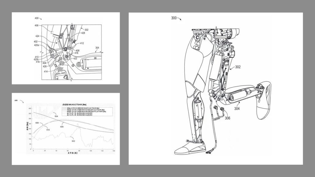
Upper Leg (Thigh 302):The robotic thigh structure, containing space (428) and mounting provisions for the linear actuator (406).
Lower Leg (Shin 304):The robotic calf structure.
First Link Member (402):A critical transmission link. One end (408) is pivotally connected to the thigh (302) via pivot (412). The other end (410) serves as a connection hub.
Second Link Member (404):Another key transmission link. One end (414) is pivotally connected to the shin (304) via pivot (422). The other end (416) is pivotally connected to the second end (410) of the first link (402) via pivot (420b). May incorporate a force sensor (426).
Linear Actuator Device (406):The core driving unit, fixed inside the thigh (302). It features a linearly movable structure (424) (e.g., pushrod/slider).
Pivot Points:
412: Hinge point between the thigh (302) and the first link (402) (First Pivot).
418: Main joint hinge point between the thigh (302) and the shin (304) (Second Pivot).
420a: Hinge point between the movable structure (424) and the second end (410) of the first link (402) (Third Pivot).
420b: Hinge point between the second end (410) of the first link (402) and the second end (416) of the second link (404) (Fourth Pivot).
422: Hinge point between the first end (414) of the second link (404) and the shin (304).
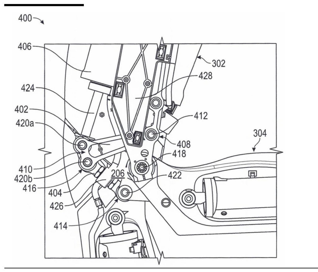
The working principle can be understood as follows: when the linear actuator (406) is activated, it pushes or pulls a movable structure (424) to perform a small linear motion. This linear motion is ingeniously converted into a large-range rotational motion of the lower leg (304) relative to the upper leg (302) through the coordination of the first and second link members (402, 404). With this design, a simple linear actuation mechanism drives the entire complex flexion-extension motion of the knee joint, embodying the engineering aesthetics of “simplifying complexity”.
Core Innovations: Biological Inspiration and Efficient Drive
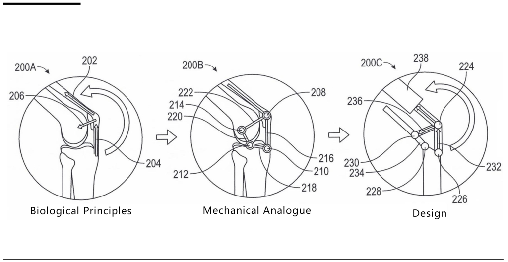
Highly Biomimetic Four-Bar Linkage Mechanism
The patent’s core lies in a four-bar linkage system that mimics the interaction mechanism of the human knee’s quadriceps-patella-tibia (corresponding to points/pivots 224–230 / 412, 418, 420a, 422 in patent Figures 2 and 4).
First Link Member (402): Simulates part of the quadriceps tendon/patellar ligament function. One end (408) is pivotally connected to the robot’s “thigh” (upper leg 302) via the first pivot (412) for rotational movement. The other end (410) attaches to the movable structure (424) of the linear actuator device (406) (via pivot 420a).
Second Link Member (404): Mimics part of the patellar ligament function. One end (414) is pivotally connected to the robot’s “shin” (lower leg 304) via pivot (422). The other end (416) connects to the second end (410) of the first link member (402) via another pivot (420b).
Linear Actuator Device (406): Serves as the “quadriceps muscle”. Its core is a linearly movable “movable structure” (424), such as a pushrod or slider, directly driving the first link member (402) via pivot (420a).
Key Pivot Connections: The thigh (302) and shin (304) are directly hinged via the second pivot (418), forming the knee joint’s main rotation axis. The shin (304) is also connected to the second link member (404) via pivot (422).
This specific layout of four nodes (thigh connection point 412, shin connection point 418, actuator connection point 420a, shin-second link connection point 422) and four links (thigh 302, shin 304, first link 402, second link 404) is crucial for biomimicking biomechanics and achieving efficient power transmission.
Single Linear Actuator Drives Large-Range Motion
This represents the patent’s most groundbreaking innovation, ingeniously leveraging the transmission ratio characteristics of the linkage mechanism. The linear actuator (406) only needs to drive the first link member (402) to rotate at a relatively small angle (approximately 60 degrees). Through the 联动 (coordinated motion) of the first link (402) and second link (404), and by transmitting motion to the shin (304), this small-angle input is amplified to drive the shin (304) to achieve an ultra-large-range (approximately 150 degrees) rotational motion relative to the thigh (302).
This drastically simplifies the drive system—requiring only one linear motor (such as a servo motor)—while reducing weight, volume, and significantly lowering energy consumption.
Patent original text: “The rotation angle range of the first link member is about 60 degrees.” “The rotation angle range of the lower part of the leg of the robot is about 150 degrees.” And “Although the rotation range of the lower leg of the robot can be about or close to 150 degrees, the linear actuator is configured or constructed to cause the rotation of the link with a smaller rotation range (e.g., about 60 degrees). This means that a relatively large rotation angle of the lower leg can be achieved through a relatively small movement of the linear actuator…” “The rotation angle range of the lower part of the leg of the robot is about 150 degrees.” And “Although the rotation range of the lower leg of the robot can be about or close to 150 degrees, the linear actuator is configured or constructed to cause the rotation of the link with a smaller rotation range (e.g., about 60 degrees). This means that a relatively large rotation angle of the lower leg can be achieved through a relatively small movement of the linear actuator…”
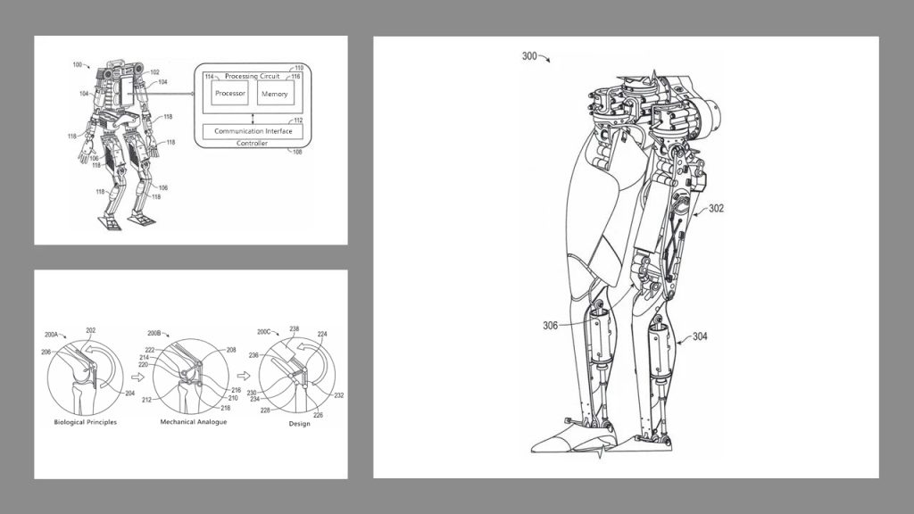
Intelligent Closed-Loop Control System
The patent not only designs the mechanical structure but also incorporates a sophisticated control system (processing circuit 110). The processing circuit (110) determines the desired posture (target angle) of the shin (304) relative to the thigh (302). Using the knee joint assembly’s unique geometric relationships and dynamic models (potentially stored as lookup tables or calculation formulas in memory 116), the circuit calculates the precise displacement required for the movable structure (424) of the linear actuator (406).
The system dynamically computes displacement in real-time, factoring in current states (e.g., instantaneous angle, velocity) and required torque for precise, adaptive control. Commands are then sent to the linear actuator (406) to drive the movable structure (424) to the calculated position, achieving the desired shin posture.
This integration of mechanics and intelligent control enables the system to mimic natural human movement while optimizing energy efficiency and responsiveness.
Technical Advantages
Based on the above innovative design, the knee joint assembly demonstrates significant advantages:
Ultra-Large Motion Range:
The lower leg can achieve a flexion-extension range of approximately 150 degrees, very close to the natural mobility of the human knee joint (typically 140–160 degrees), greatly enhancing the robot’s movement flexibility and human-likeness.
Patent original text: “The knee joint assembly described herein allows the lower part of the robot’s leg to have a range of rotation similar to that seen in humans… about 150 degrees (e.g., between 140 degrees and 160 degrees).”
High Energy Efficiency:
Driven by a single linear actuator that only needs to operate efficiently within a small angle (60 degrees), combined with an optimized linkage design, overall energy consumption is significantly reduced.
Patent original text: “The knee joint assembly described herein can be driven by a single linear actuator and enables minimizing or reducing power usage, or maximizing or improving efficiency, while still meeting torque, speed, and motion range requirements.” And “Knee joint assembly 400 was simulated with different parameters, and parameters leading to the least power consumption by actuator 406 were determined.”
Compact and Simplified Structure:
The single-actuator design and optimized linkage layout make the entire knee joint assembly more compact, lighter in weight, and more reliable.
Patent original text: “A relatively large rotation angle of the lower leg can be achieved through a relatively small movement of the linear actuator, which allows for a compact design of the knee joint.”
Optimized Mechanical Performance:
The bionic design helps achieve knee joint movement trajectories and mechanical properties closer to those of humans, reducing issues caused by poor geometric structures and improving motion smoothness and reliability.
Patent original text: “Knee joint assembly 400 enables the lower part 304 to perform such a large-range rotational motion without poor geometry and with relatively high efficiency.”
Sensing and Integration:
A force sensor (426) can be integrated into the second link member (404) to measure the force on the joint, providing feedback for control algorithms to achieve smarter and safer motion control.
Patent original text: “In some embodiments, the second link member 404 may include, for example, a force sensor 426 to measure forces on the second link member 404.”
Summary
The core essence of Tesla’s robotic knee joint patent (CN120152903A) lies in “bionic design + efficient transmission”. It creatively draws on the four-point mechanical model of the human knee joint (interaction among femur, patella, tibia and ligaments), and transforms it into an ingenious four-bar linkage mechanical structure (first link 402, second link 404, thigh 302 and lower leg 304). Its most revolutionary breakthrough is that by only using one linear actuator (406) to drive the first link member (402) to rotate at a small angle (about 60 degrees), and through the ingenious design of lever transmission ratio, it can efficiently drive the lower leg (304) of the robot to achieve large-angle (about 150 degrees) flexion and extension movements close to the human range of motion. This design solves the pain points of traditional robotic knee joints, such as limited range of motion, complex structure and high energy consumption, and realizes compact structure, efficient drive and anthropomorphic movement. With the real-time displacement calculation and control of the integrated force sensor (426) and intelligent processing circuit (110), the knee joint assembly has laid an important technical foundation for humanoid robots (such as Tesla Optimus) to achieve more natural, flexible and energy-saving movement capabilities, and significantly improved their practicability and battery life in complex environments.
Patent Drawings